As result of the ATL M2M CIM to PIM transformation process, you get the space reference, information flow and entity context model depicted in Figure 40, Figure 41 and Figure 42.
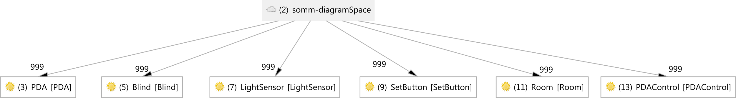
The referential space model is depicted in the Figure 40.
The somm-diagramSpace space represents the root space where all elements in the system are aware of all the information in the system. The entity references that are immersed on this referential space are:
- PDA This entity reference represents the set of PDA entities in the system
- Blind This entity reference represents the six blinds in the system
- LightSensor This entity reference represents the two light sensors in the system
- SetButton This entity is in charge of sensing user desire of setting the light intensity in the current room.
- Room This entity represents the location sensor.
- PDAControl This entity represents the set of entities available on the PDA.
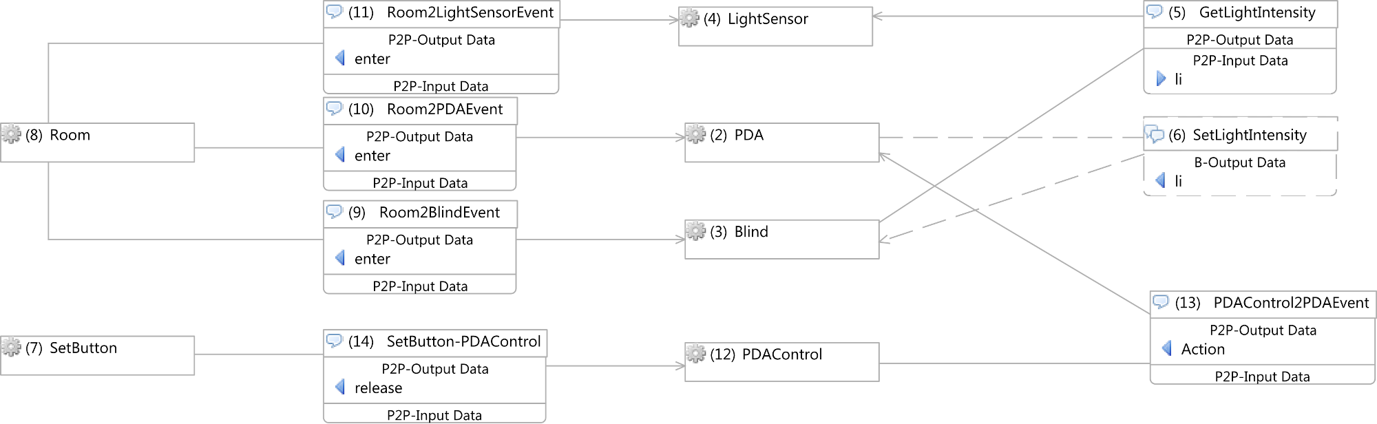
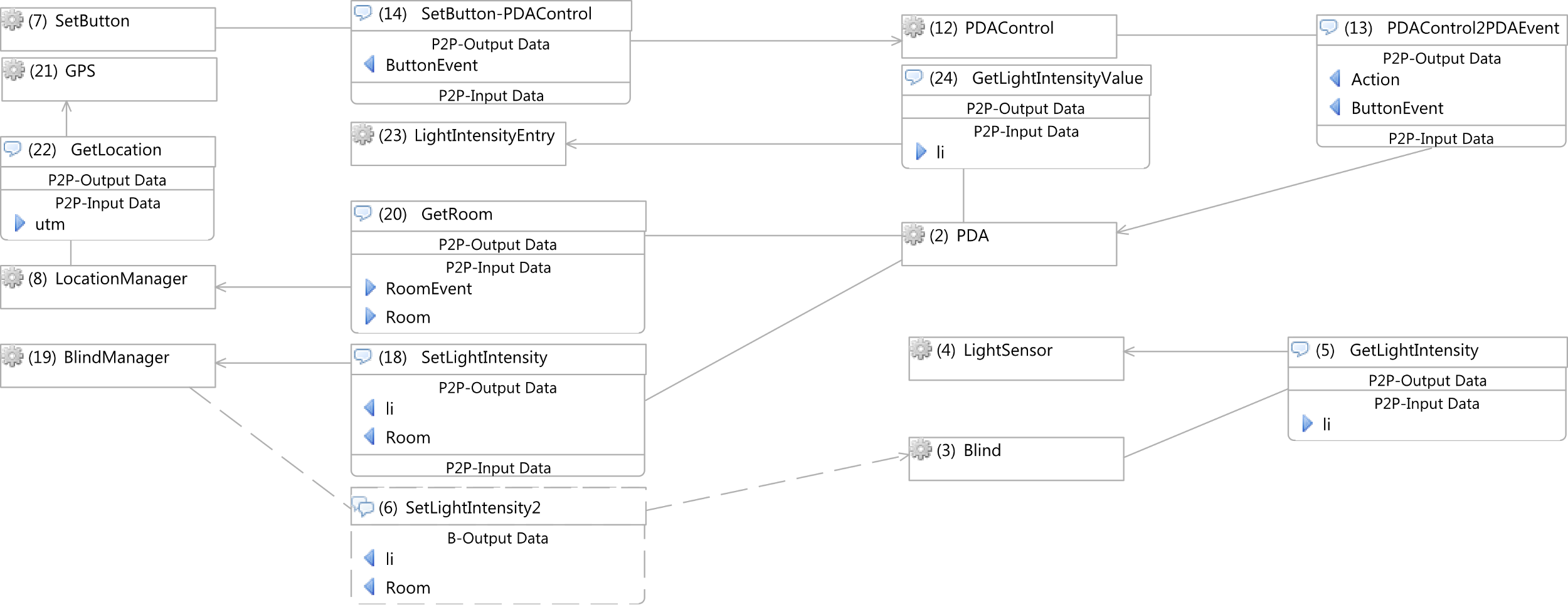
The information flow model depicted in the Figure 41 represents the basic information flows of the system where we can find the following information flows:
- Room2LightSensorEvent The Room2LightSensorEvent information flow notifies light sensors of their location.
- Room2PDAEvent The Room2LightSensorEvent information flow notifies PDAs of their location.
- Room2BlindEvent The Room2LightSensorEvent information flow notifies blinds of their location.
- SetLightIntensity The Blind-SetLightIntensity information flow sends the user desired light intensity of the current room from a PDA to a set of blinds.
- GetLightIntensity The GetLightIntensity information flow requires the actual light intensity in the room.
- SetButton-PDAControl The SetButton-PDAControl information flow expresses the used desire to change current room light intensity.
- PDAControl2PDAEvent The PDAControl2PDAEvent information flow forwards the event to the PDA.
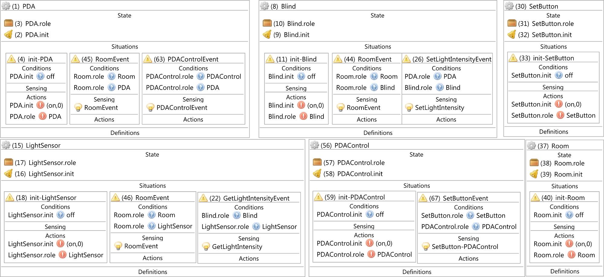
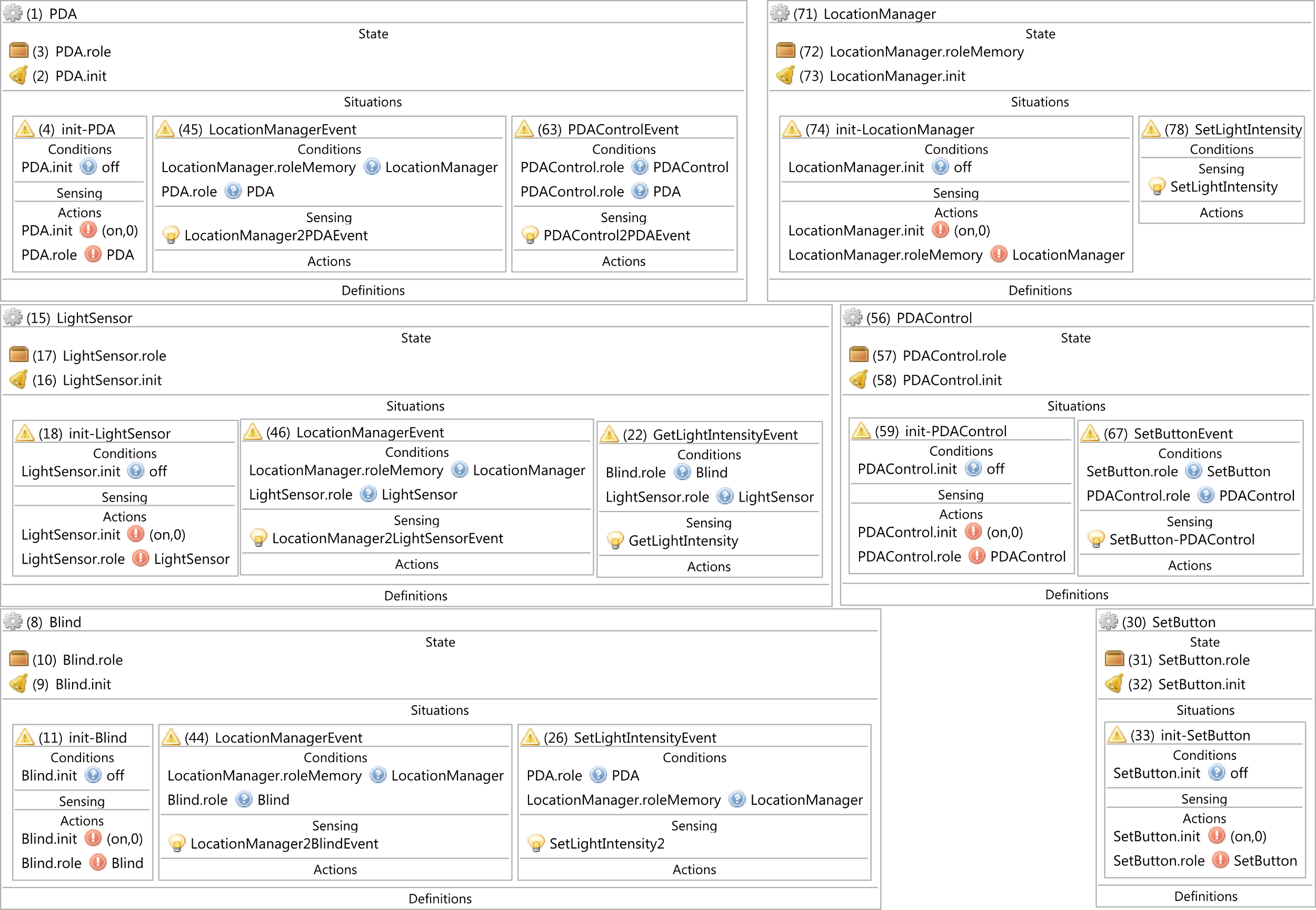
The entity context model depicted in Figure 42 contains information that describes entities defined on the referential space and information flow models. Each entity context defines the initialization situation that is characterized by its name (init-entityname) that sets initial values to memories. This situation is bound to the initMemory that is used to execute it once. They also define a situation for each task they are involved. Each of these situations defines a set of condition that define the context the situation arises, and a set of actions that define new state on
context memories. Besides, a situation is defined for each event that an entity is aware of. These events are characterized by their names (entity nameEvent). Finally, the set of variable definitions that are used by situations is included into the entity.
Limiting broadcasting
According to the referential space model exposed on Figure 40 all entity references have a MANY-TO-MANY relationship. Therefore, all information on the system is known by all entities leading to information network overloading and among many other disadvantages.
For instance, light sensors are used to capture the light intensity of a room. According to the space reference model depicted on Figure 40, the light intensity information of a room is delivered to all blinds. This leads to an incompatibility with the information flow model exposed in Figure 41.
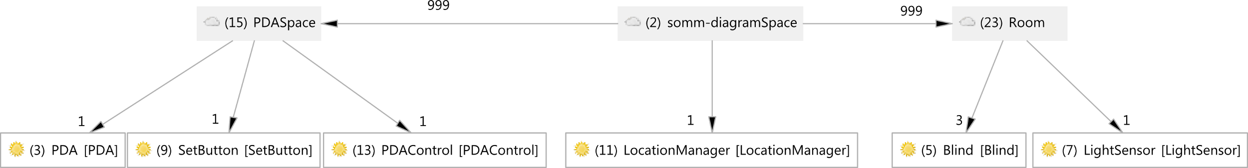
To avoid this situation apply the Session Modeling pattern defining the Room referential space, as can be seen on Figure 44. This change has no impact on the information flow and the entity context models. However, as consequence of this change, we have to apply the Information Exchange pattern among different referential spaces. The consequences of applying this pattern in the information flow model are depicted on Figure 44, Figure 45 and Figure 46.
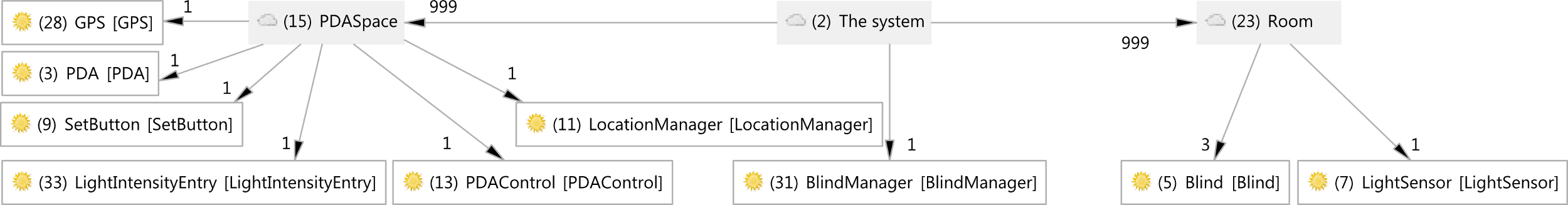
As result we have performed the following modifications to the Space Reference model (see Figure 44):
- The communication between the PDA entity and the Blind entities is performed through the LocationManager entity. Therefore, we have created a referential space that represents the PDA space (PDASpace) containing references to: PDA, SetButton and PDAControl entity references.
- The Room entity reference, that is in charge of providing location features to PDA, Blind and BlindSensor entity references have been renamed to LocationManager to improve model readability.
- We have also created the Room referential space which contains entity references that belong to a room (i.e. Blind and LightSensor entity references).
These modifications also affect the information flow model in the following ways (see Figure 45):
- The SetLightIntensity information flow that goes from the PDA entity to the LocationManager was replaced by by the SetLightIntensity point-to-point information flow that goes from the PDA entity to the LocationManager entity and the SetLightIntensity2 broadcast information flow that goes from the LocationManager to the Blind entities.
- The Room entity was renamed to LocationManager
- The Room incoming/ongoing information flows were renamed by replacing the Room prefic with the LocationManager prefix

Finally, to limit the information broadcasting, the following changes where performed on entity context model (see Figure 46):
- The Room entity was renamed to LocationManager.
- The SeLightIntensity situation was added to the LocationManager entity.
- The SeLightIntensity situation was renamed to SetLightIntensity in the Blind entity.
- The situations and sensing conditions were renamed according to the replacement of Room by LocationManager.
Location system optimization
The goal of this section is the optimization of the location system. The LocationManager entity plays the role of the location system. As can be seen on the information model depicted on Figure 45, the LocationManager entity provides information to three entities (Blind, PDA and the LightSensor). However, two of them (the Blind and the LightSensor entities) do not need this information because of their nature. They are fixed to a room. Therefore, we will remove the LocationManager2LightSensorEvent and LocationManager2BlindEvent information flows (see Figure 48). As result of this change we note that the only entity that «needs» the LocationManager entity is the PDA entity. Therefore, we «move» the LocationManager to the PDASpace referential space.
This change leads to the addition of the BlindManager entity reference that will play the role of intermediary between PDA entities and Blind entities. The impact of these modifications in the
reference model is depicted on Figure 47. As consequence of these changes, in the information flow model we replace the LocationManager2PDAEvent broadcast information flow (see Figure 45) by the GetRoom point-to-point information flow applying the Pooling pattern. The result of this modification is shown on Figure 48.
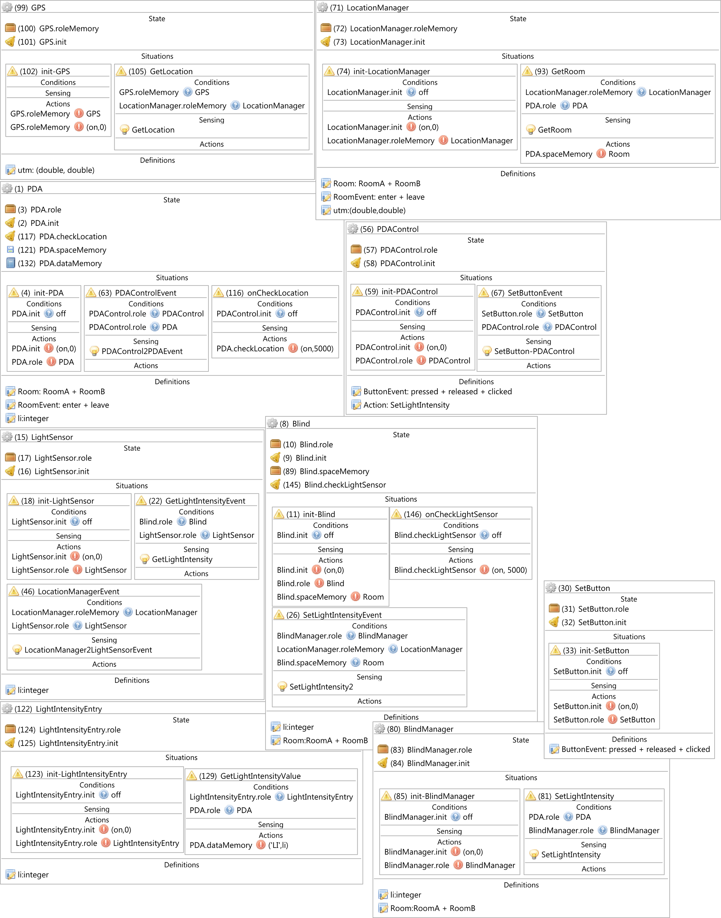
Changes on the information flow model affect the entity context model. So, we remove the LocationManagementEvent situation from the PDA entity context, and add the GetRoom situation to the LocationManager. Besides, we remove the LocationManagerEvent situations from the LightSensor and the Blind entity contexts, too.
Due to the introduction of the BlindManager entity, will the SetLightIntensity situation from the LocationManager entity, and we add it to the BlindManager.
Changes on entity context model are depicted on Figure 49.
Sensing the location
The LocationManager plays the role of location system. So, it should be able to capture PDA location. To carry out this task, it needs information from a sensor capable of acquiring this position.
One way to get it is using a GPS. Therefore, to get this position the LocationManager entity requests UTL coordinates from the GPS entity through the GetPosition point-to-point information flow.
These coordinates are turned into rooms and events (i.e. enter or leave) by the LocationManager entity and sent to the PDA entity as requested by the GetRoom point-to-point information flow.
Thus, we include the GPS entity reference under the PDASpace referential space of the referential space model of the system (see Figure 47).
The influence of this change in the information flow model is depicted on Figure 48 where we have added the GPS entity and the GetLocation point-to-point information flow from the LocationManager entity to the GPS entity in order to get the UTM coordinates of the PDA. As consequence, we have added the GPS entity context to the entity context model of the system. It defines the GetLocation situation to return the UTM coordinates to the LocationManager entity. Results are exposed on Figure 49.
To update the user position we have applied the Pooling pattern. Thus, we have added the onCheckLocation situation to the PDA entity context.
Sensing the illumination
In this case the modification affects the entity context model of the system only.We have only added the onCheckLightSensor situation to implement the Pooling pattern. Results are exposed on Figure 49.
Adding controls
In order to set the light intensity on a room, users have to:
- Fill in a text field with the desired light intensity
- Press a button on the PDA screen
Note: we have used a text field, but the same applies to a slide bars or any other control. Although the button has already been included, the entry control is missing. So, we have added the LightIntensityEntry entity to the system that provides the light intensity value from the user. Thus, we have added the LightIntensityEntry entity reference to the PDASpace referential space in
the referential space model diagram (see Figure 47). As consequence, we have added the LightIntensityEntry entity to the information flow model jointly with the GetLightIntensityValue point-to-point information flow that comes from the PDA entity (see Figure 48).
Finally, we have added the LightIntensityEntry entity context that defines the GetLightIntensity-Value situation to return the light intensity value (li) to the PDA entity (see Figure 49).