As result of the ATL M2M CIM to PIM transformation process, you get the space reference, information flow and entity context model depicted in Figure 54, Figure 55 and Figure 56.
The referential space model is based on a common referential space and three entity references (Figure 54). The referential space (The system) represents a single space where all elements in
the system are aware of all the information in the system. The entity references that are immersed on this referential space are: the PDA entity reference that represents the set of PDA entities in the system, and the CardiacPulseSensor entity reference that represents the cardiac pulse sensor in the system (the PDA owner).

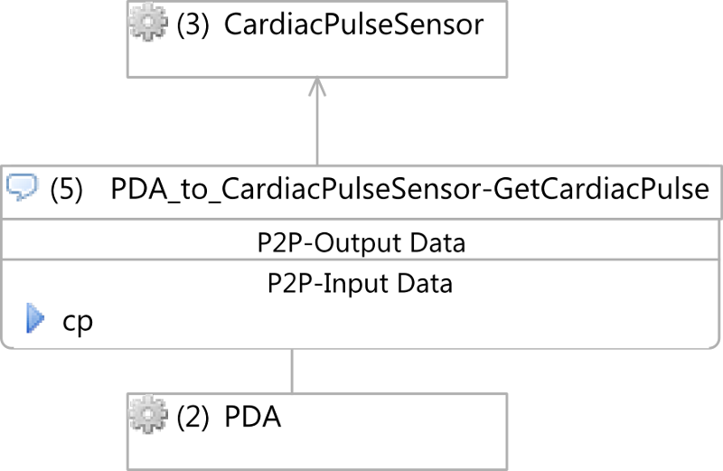
The information flow model (Figure 55) has only one information flow that is a point to point information flow representing a ONE-TO-ONE relationship.
The CardiacPulseSensor to PDA-GetCardiacPulse information flow sends the bpm of the PDA owner from the cardiac pulse sensor to the PDA.
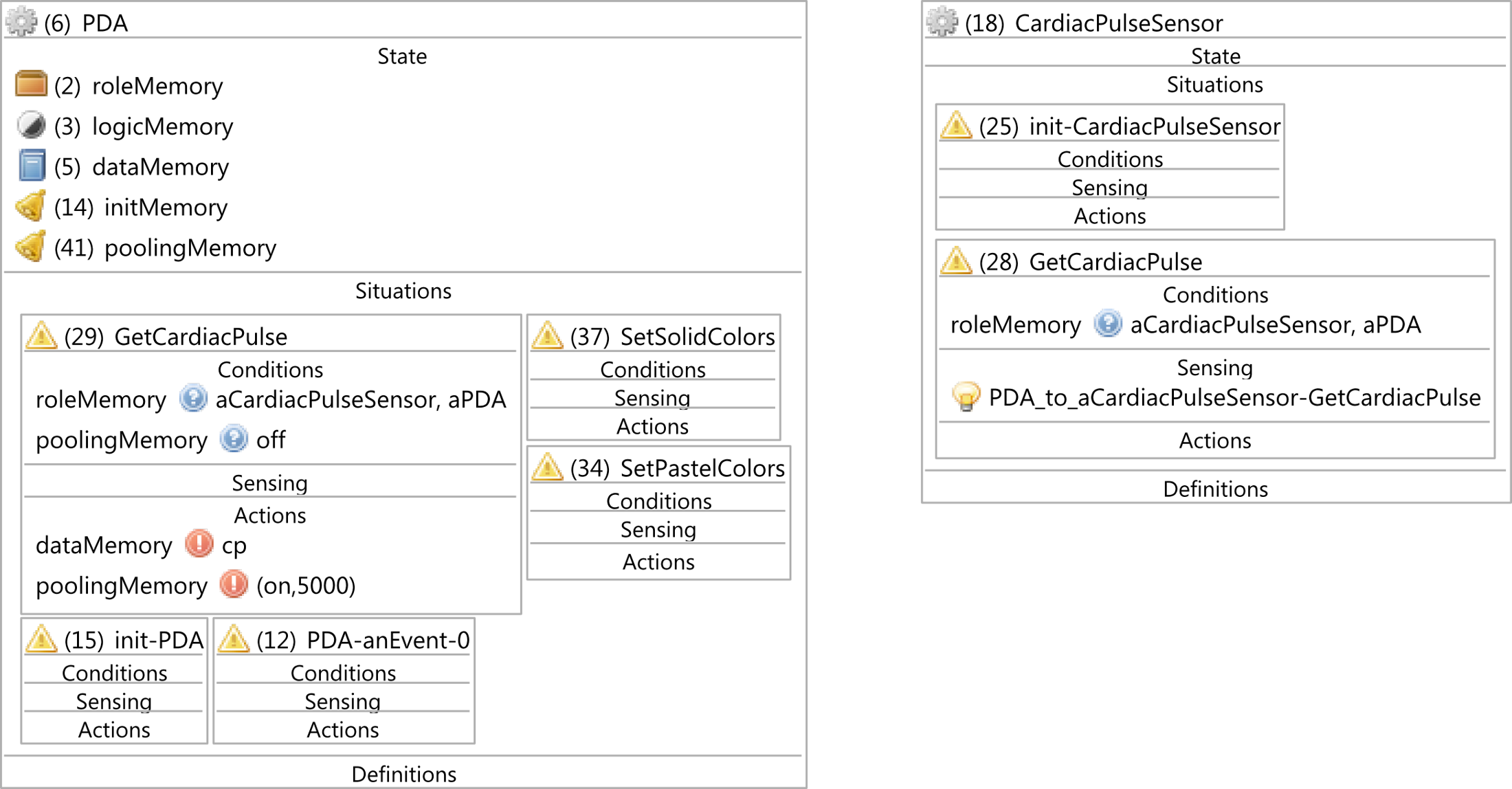
The entity context model contains information that describes entities defined on the referential space and information flow models. Each entity context defines the initialization situation that is characterized by its name (init-entity name) that sets the initial values to memories. This situation is bound to the initMemory that is used to execute it once. They also define a situation for each task they are involved. Each of these situations defines a set of conditions that defines the context the situation arises, and a set of actions that define new state on context memories. Besides, a situation is defined for each event that an entity is aware of. These events are characterizedbby their names (entity name-anEvent-a sequence number). Finally, the set of variable definitions that are used by situations is included into the entity. Figure 56 depicts the entity context model of the application.
Although these models provide designers with an overview of the software structure and relationships; the information can be customized to include or modify software characteristics to the system. In order to describe the information flow model we modify the model derived from the transformation.
From event-driven sensing to polling
The Figure 54 and the Figure 56 depict the relationship between the senson and the PDA using the event-driven pattern. However, due to software design strategy we decided to turn it into a polling based sensing system.
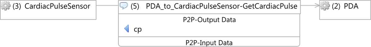
In the information flow model depicted on Figure 55 the direction of the information flow CardiacPulseSensor to PDA-GetCardiacPulse that goes from the CardiacPulseSensor to the PDA is turned to
go from the PDA to the CardiacPulseSensor. So, the entity that has the control of the information flow is the PDA instead of the cardiac pulse sensor. As consequence this information was renamed
to PDA to CardiacPulseSensor-GetCardiacPulse. Besides, the cp output data was turned into input data because of the inversion of the information flow control. The changes performed on the Information Flow model are depicted on Figure 57.
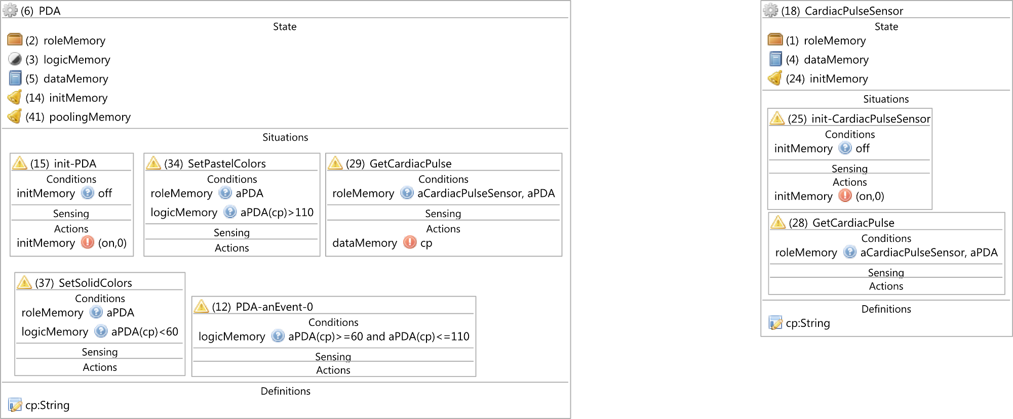
The changes performed on the entity context model are related to the modification of the sensing information flow which location has been changed from the GetCardiacPulse of the PDA entity to the same situation on the CardicPulseSensor entity. Besides, we have included a time memory (poolingMemory) on the PDA entity to pool the cp value. The GetCardiacPulse situation on the PDA entity also includes the condition and actions to perform the pooling sensing. The result of this modification is exposed onm Figure 58.