Once the PSM (Information Flow, Space Reference, Entity Context and Deployment models) is built the final step is performing the MOFScript M2T transformation to generate source code.
Context-aware applications for ubiquitous computing environments are characterized by:
- A Context-aware System (CAS) is composed of a set of distributed CAAs, instead of a single application.
- CAAs should be deployed on heterogeneous platforms.
- CAAs should embrace connectivity alternatives.
- Entities should be able to perceive the environment and act accordingly.
- Multiple devices should be able to get through and coordinate activities to accomplish system goals.
- Entities should be able to be part of a society of entities.
- Entity location is part of the environment.
- Entities should be aware of the task being performed in order to provide assistance.
Due to these characteristics, the diversity of frameworks/systems to build this applications is huge (programming languages, platforms, communication systems, etc). Each framework/system is designed to address particular characteristics of this type of applications. Therefore, the definition of a fully fuctional framework makes no sense.
Therefore, we define the Underlying Infractucture characteristics required to run CAS generated by the MOFScript M2T transformation process. Thus, developers are free to choose the programming language, platform, etc. according to project requirements.
Underlying infrastructure
The basic elements of the underlying infrastructure supporting this architecture is depicted on Figure 61.
An entity uses a set of memories that store information related to the environemnt to perceive it. Five types of memories are employed to express the entity context state. The social memory is usually represented by a Holder memory that keeps the role of the entity, the data memory is usually defined by a Dictionary memory that keeps key-value pairs, the logic memory keeps logic expressions to define conditions and the task and space memories keep track of the tasks and spaces entities have gone through, therefore we employ Stack memories to represent these paths.
These memories are updated through implicit information flows that are not exposed on the information flow model because they are part of the underlying infrastructure of the system. This infrastructure runs in a thread that is independent from the application main thread.
This infrastructure provides the following services:
- Distributed time service that provides entities with synchronized clocks. This is a very important issue due to the fact that sequence is taken into account in expressions.
- Each entity is assigned to a unique id. This issue can be easily implemented using an IPv6 Internet address.
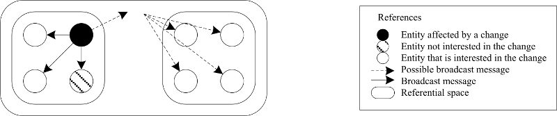
The Communication infrastructure to provide these services is based on a message broadcasting computational model. Therefore, the communication infrastructure propagates entity changes when the entity state change. The assimilation of these changes by other entities depend on the entity that is notified of a change.
When a memory is updated, a situation can be executed.
A situation is defined by the following elements:
- A situation name that identifies an entity context relevant state of the environment
- A set of contextual conditions that define the state of the environment
- A set of sensing conditions that may define a set of information flows or events from other entities that may be used to fire the situation
- A set of actions that define a contextual reaction if the situation arises
The situation execution is performed as follows:
- Sensing condition evaluation. When a set of sensing conditions matches, then memory conditions are evaluated. If no sensing condition is defined, then conditions are evaluated straight-forward.
- Condition evaluation. When the set of conditions is satisfied, then the set of actions on output variables defined by the information flow (referenced by sensing conditions) are executed. If no condition is defined, then actions are executed straightforward. Note that these conditions can be evaluated according to: (a) the entity context internal state (memories), (b) the entity context of synchronized entities (memories). We have denoted synchronized entities to those entities that are related to this situation through sensing conditions (information flows), or (c) the information flow output variables.
- Execution of actions on output variables defined on information flows (referenced by sensing conditions).
- Execution of the situation on the entity context core. The situation is able to use information flow output variables as input parameters and information flow input variables as output parameters (only available if it is a point-to-point information flow).
- Execution of actions on input variables defined on information flows (referenced by sensing conditions)
Conceptual Architecture
The idea behind the definition of the conceptual architecture is the definition of abstract classes and interfaces capable of supporting the underlying infrastructure.
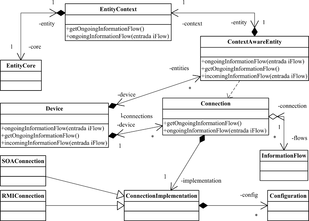
While the UML class diagram depicted in Figure 62 describes the structural characteristics of the architecture, the Sequence diagrams depicted in Figure 63 and Figure 64 show the behavior of the architecture. The architecture follows the producer-consumer paradigm. The producer as well as consumer process are an implementations of the Chain of responsibility design pattern [4].
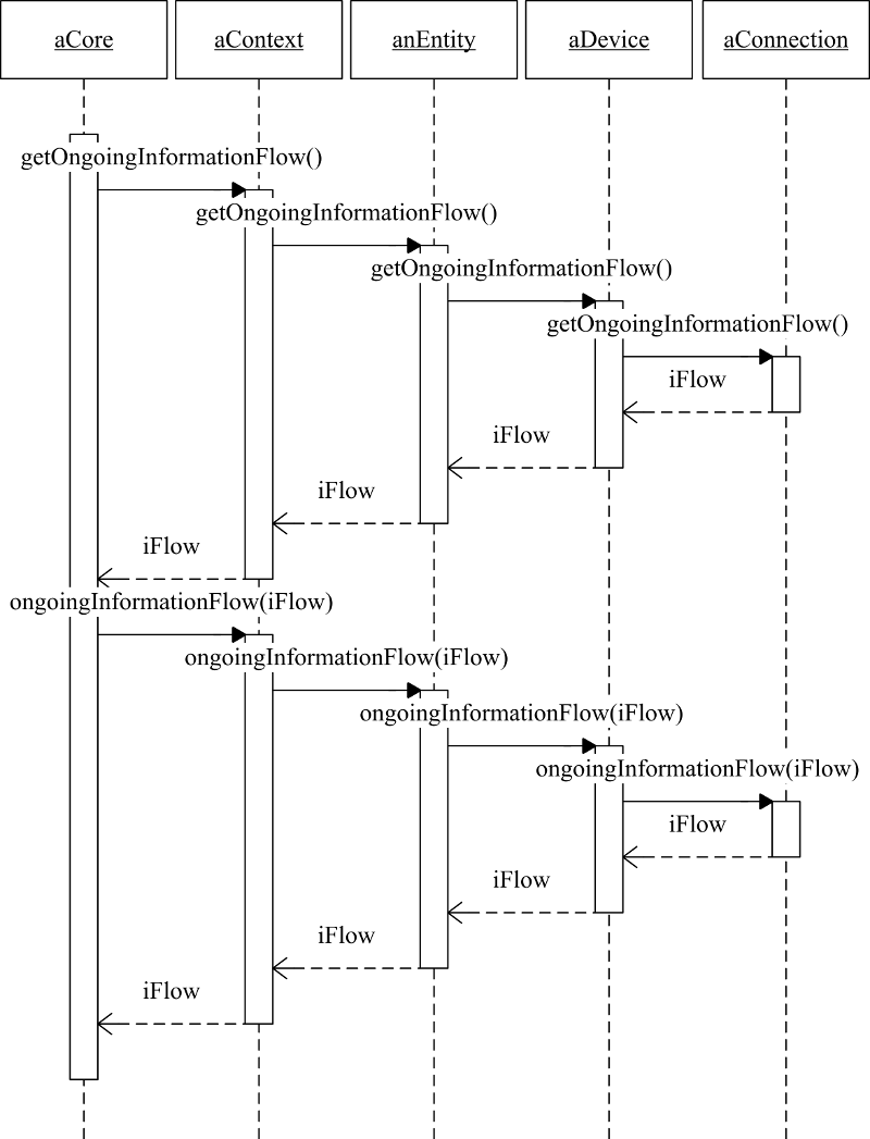
The production of information (see Figure 63) begins in the EntityCore class. This information can be consumed by the same entity, if it only affects the producer entity; or it can be turned into an information flow, if it affects other entities. The information flow is represented by the InformationFlow class which instances are created from a Connection class instance. Therefore, the EntityCore class instance asks for it to the context (represented by the EntityContext class). It forwards the call to the entity (represented by a ContextAwareEntity class instance) that finally asks to the Connection class instance for the information flow. Then, the Connection class instance returns an InformationFlow class instance according to parameters set by the entities in the chain we have just described. The information flow is then sent back all the way back to the entity core. During this path back to the core, the information flow populated with information that is generated by intermediaries. Once the information flow was generated and populated with information in the core, the flow follows the same path that was followed when it was created to the connection again. Again, during this path, the flow may be populated with additional information according to the information provided by the core. Once, it has arrived to the connection it is sent to the target/s entity/ies through the network.
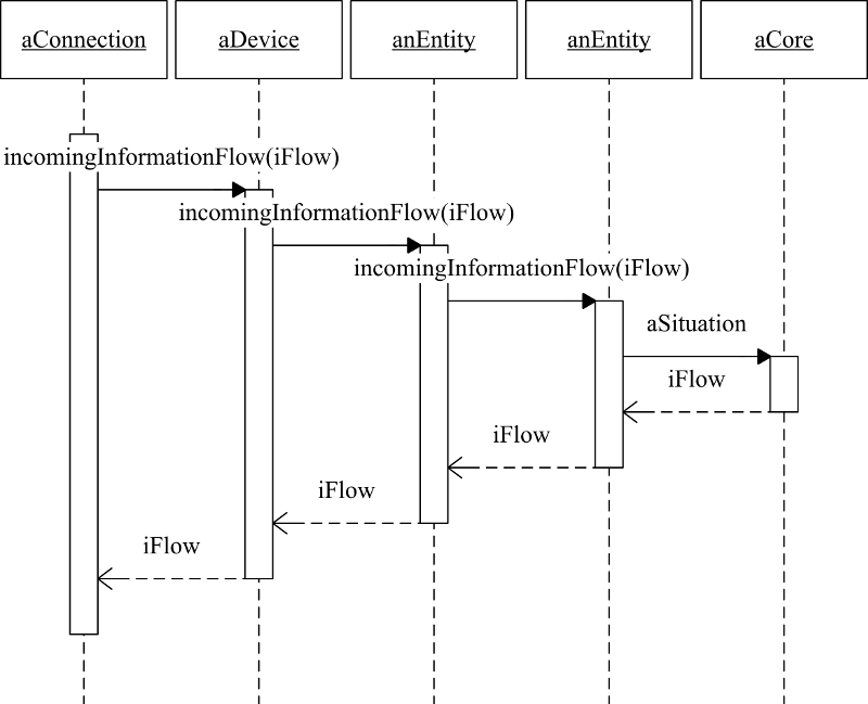
The consumption of information (see Figure 64) starts when the information flow arrives to the target entity, a Connector class instance consumes it. To perform this task, it sends the information flow the associated Device class instance. It gathers information from the information flow and may eventually modify it. Then, this information flow is sent to a ContextAwareEntity class instance. Once there, the entity is able to gather or modify information of the flow before forwarding it to the entity context (represented by an instance of the EntityContextclass). Again, the context is able to gather or modify information before it is processed by situations (see Section 6.3) and reaches the core of the entity (represented by an instance of the EntityCore class). Depending on type of the information flow (broadcasting or point-to-point), the information flows the way back to the connection before the consumption process finishes.
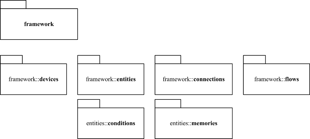
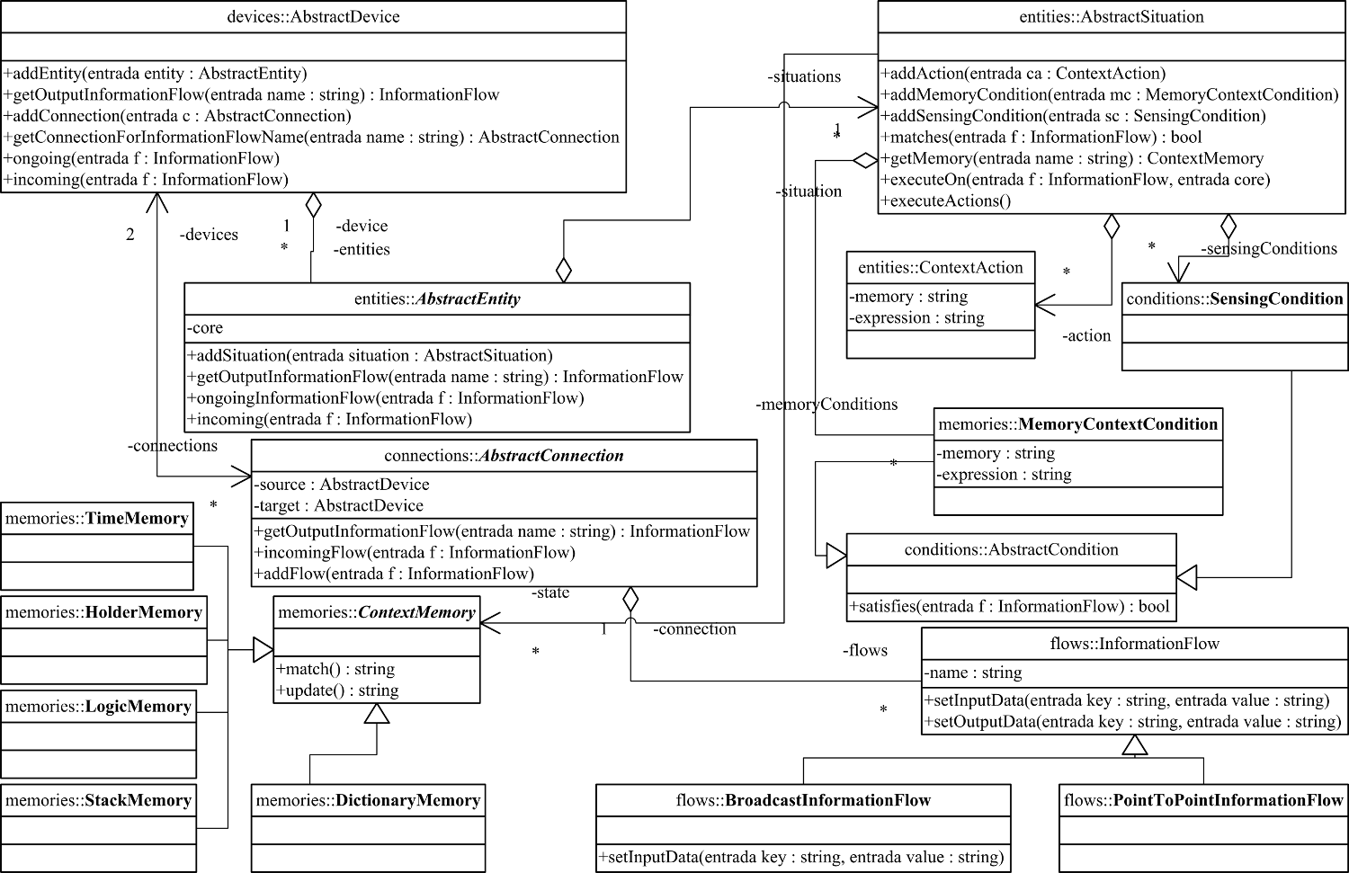
To demostrate that the code generated by the MOFScript M2T transformation process represents an application complies the conceptual architecture, the conceptual architecture was implemented in Java. A package diagram of the abstract architecture is depicted in Figure 65 and a refined class diagram is exposed in Figure 66.
You can reference this work as:
Ricardo Tesoriero, José A. Gallud, María D. Lozano and Víctor M. R. Penichet. CAUCE: Model-driven Development of Context-aware Applications for Ubiquitous Computing Environments. Journal of Universal Computer Science, Vol. 16, No. 15, pp. 2111-2138. 2010. Link: http://www.jucs.org/jucs_16_15/cauce_model_driven_development