To define the CIM model (Analysis Layer models), we start describing the Social Model, then the Space and Task models.
Social Model
The Figure 51 shows the social model of this application. As this application does not have many actors on scene, it is a quite simple model that defines two roles:
- PDA The PDA represents the device that is able to process the bpm (beat per minute) acquired from the CardiacPulseSensor and act as consequence.
- CardiacPulseSensor The CardiacPulseSensor is in charge of acquiring the bpm of the PDA owner to be analyzed by the PDA.
The model also defines two instances one for each role (aCardicPulseSensor, aPDA). These instances are not necessary because the system is designed for a single user and it is capable of be used with
only one PDA.

The space model
The space model is even simpler than the social model, because it not a location aware application (at least for this simple example). The space model is depicted on Figure 52. However, the system could be easily extended to be adapted to the user or the place it is in. For instance, suppose that we the upper and lower limits of bpm are modified according to the space the PDA is into (these values may not be the same if the PDA owner is into a stadium as he/she is his/her bedroom).

The task model
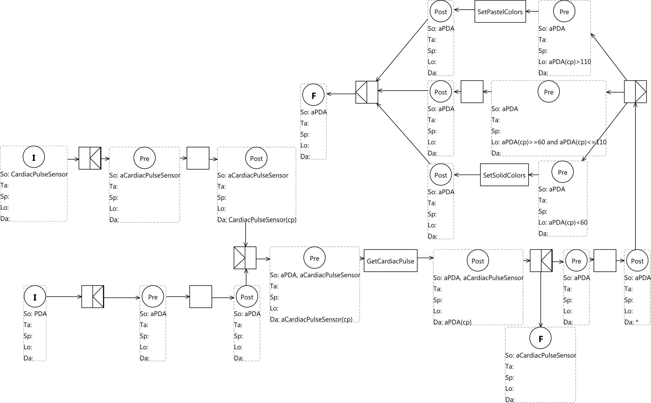
From the scenario representation on Figure 53 the system should be capable of performing three basic tasks: GetCardiacPulse, SetPastelColors and SetSolidColors.
In order to perform them, the task model depicted on Figure 53 was created. To describe this model we follow the workflow from initial conditions. First, we describe the path that starts with the initial condition that defines the CardicaPulseSensor social expression. This expression points out that the group of cardiac pulse sensors are represented as one token. Although this distinction is quite important in most of the models, it is no so important on this scenario because we have set that there is only one instance in the system for each role. However, to be prepared for future extensions, we have decided to explicitly get one instance of the CardiacPulseSensor role by defining the aCardiacPulseSensor social expression of the precondition after the and-split route task.

The value of the PDA owner cardiac pulse is defined by the cp variable on the data expression and «waits» for synchronization to aPDA. Once this synchronization, defined by the and-join route task is performed, the GetCardiacPulse simple task is performed, sending the cp value from the cardiac pulse sensor to the PDA. Once the communication has finished, the aCardiacPulseSensor is sent to a final condition to be reinserted into the workflow.
The second path to be analyzed is the one where the initial condition defines the PDA social expression. As in the case of the first path, to be prepared for future extensions, we have decided to
explicitly get one instance of the PDA role by defining the aPDA social expression of the precondition after the and-split route task. Thus, when the aPDA and aCardiacPulseSensor instances synchronize the cardiac pulse value (cp) is received by the PDA from the cardiac pulse sensor. Once the PDA has the cardiac pulse value, the split alternative pattern is applied.
There are three possible paths to follow:
- The one that performs the SetPastelColors simple task which is followed if the cardiac pulse obtained from the cardiac pulse sensor is lower than 60.
- The one that performs the SetSolidColors simple task which is followed if the cardiac pulse obtained from the cardiac pulse sensor is higher than 110.
- The one that does not perform any task that is followed if the cardiac pulse obtained from the cardiac pulse sensor is lower than 110 and higher than 60.
Finally, the workflow starts over again by going into a final condition.